Agent Graphs and State Machines Explained
Agent behavior often looks like a loop, but production systems need more than “keep calling the model until it finishes.” They need explicit branches, legal transitions, checkpoints, terminal outcomes, and recovery paths.
An [agent graph](/glossary/agent-graph/) represents work as nodes connected by edges. A [state machine](/glossary/state-machine/) represents allowed states and the events or conditions that move execution between them. Together, these patterns turn implicit prompt logic into visible, testable control flow.
This article explains both architectures and shows why a node does not need to be an agent—and why a graph does not automatically make a system multi-agent.
TL;DR
- A graph models units of work and the paths between them.
- A state machine models valid execution states and transitions.
- Nodes can contain code, tools, humans, model calls, or complete agents.
- Deterministic transitions are best for policy and known rules; model-driven transitions help with semantic ambiguity.
- Graphs and state machines improve resumability, debugging, safety, and evaluation when the flow has meaningful branches or waits.
Agent graph architecture
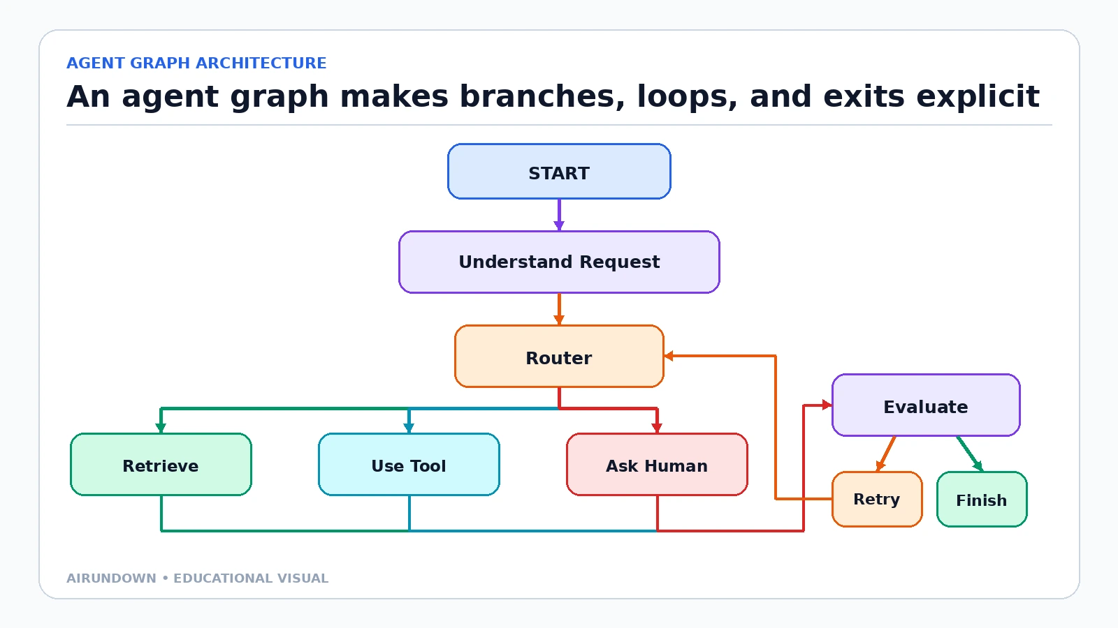
The graph exposes the permitted paths. A retry returns to a defined node instead of restarting an uncontrolled loop.
The example graph contains:
- a start point;
- a request-understanding node;
- a router;
- three possible action branches;
- an evaluation node;
- retry and finish transitions.
The model may choose a branch, but the graph limits the choices. The runtime knows where execution is, what state each node receives, and which transitions are valid.
What is a graph?
A graph consists of nodes and edges.
- Node: a unit of computation or work.
- Edge: a transition from one node to another.
- Conditional edge: a transition selected from a condition or decision.
- Terminal node: an endpoint that completes, fails, cancels, or otherwise stops the run.
Graphs are useful for non-linear processes. Unlike a simple list of steps, they can represent branching, loops, parallel fan-out, joins, and escalation.
The LangGraph Graph API uses the same core vocabulary: shared state represents the current application snapshot, nodes perform work and return updates, and edges determine what executes next.
Not every node is an agent
A node can be:
- a deterministic function;
- a database query;
- an API call;
- a schema validator;
- an LLM inference;
- a complete tool-using agent;
- a human approval wait;
- a subgraph.
This is one of the most important architectural boundaries. “Agent graph” describes the control structure, not the type of every node.
Use ordinary code for exact work. A node that verifies whether an amount exceeds a threshold does not need a language model. Reserve model judgment for unstructured interpretation, synthesis, or adaptive decisions.
What is state?
[Agent state](/glossary/agent-state/) is the current operational snapshot used across nodes. A support workflow might store:
- user identity and permissions;
- original request;
- classification;
- retrieved evidence;
- selected tools;
- tool results;
- retry count;
- active owner;
- approval status;
- final response.
Each node should read the fields it needs and return explicit updates. The runtime validates and merges those updates.
State is not the graph. The graph defines possible paths; state records this run’s current information. The same graph can execute thousands of runs with different state.
Edges and transitions
An edge answers “What may run next?” A transition occurs when execution actually moves along that edge.
Deterministic edge
Code selects the path from a known rule:
- approval required if amount exceeds a threshold;
- retry if the error is transient and attempts remain;
- finish if validation passes.
Model-driven edge
An LLM selects from allowed routes:
- billing, technical, or policy specialist;
- retrieve more evidence or produce the answer;
- ask a clarifying question or proceed.
Model output should map to a bounded route. If the model emits an unknown label, the graph should use a fallback rather than invent a node.
Conditional edge
A conditional edge can use either deterministic or model-derived state. The condition should be observable and testable.
For example, a model may classify a request into a structured field, while code validates the field and selects the permitted destination.
Loops and stopping
A loop returns execution to an earlier node. It is useful for:
- retrying a transient tool error;
- gathering more evidence;
- revising an invalid output;
- requesting missing user information;
- reflecting and replanning.
Every loop needs a [stopping condition](/glossary/stopping-condition/):
- maximum attempts;
- deadline;
- token or cost budget;
- no-progress detection;
- policy boundary;
- successful validation;
- human escalation.
Without a stopping condition, a visible graph can still produce an infinite agent.
What is a state machine?
A state machine defines a set of states and the permitted transitions between them. It focuses on lifecycle rather than work topology.
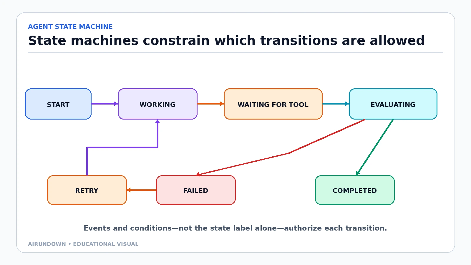
Events and conditions authorize transitions. A state name describes the current lifecycle position; it does not decide the next state by itself.
Example states:
STARTWORKINGWAITINGFORTOOLEVALUATINGCOMPLETEDFAILEDRETRY
Events may include:
task_started;tool_called;tool_succeeded;tool_failed;evaluation_passed;evaluation_failed;retry_allowed;retry_exhausted.
The state machine prevents illegal transitions. A run should not move from START directly to COMPLETED unless the architecture explicitly allows that case.
State machine vs agent state
These terms are easy to confuse:
- Agent state: the data snapshot—goal, messages, results, counters, approvals.
- State machine: the lifecycle model that defines valid states and transitions.
The state machine may use fields inside agent state to evaluate a transition. For example:
status = FAILED and retry_count < 2 permits FAILED → RETRY.
The state machine is a control model. Agent state is run data.
Graph vs state machine
A graph emphasizes work units and routing:
Understand → Retrieve → Evaluate → Answer
A state machine emphasizes lifecycle:
WORKING → WAITING → EVALUATING → COMPLETED
They can describe the same system at different levels. A graph node can place the run in a state, and a state transition can determine which graph node becomes runnable.
Use a graph when the main question is “Which work happens next?” Use a state machine when the main question is “Which lifecycle transitions are allowed?” Use both when durable work has non-trivial topology and lifecycle.
Agent graph vs agent workflow
An [agent workflow](/glossary/agent-workflow/) is the task process. A graph is one way to represent and execute that process.
A workflow can also be implemented as:
- sequential code;
- event handlers;
- a queue and workers;
- a state machine;
- a workflow engine;
- a graph runtime.
Calling a process a graph is useful only when nodes and edges clarify branching, loops, concurrency, or reuse. A four-step straight line may be easier to understand as a sequence.
Graph vs agent loop
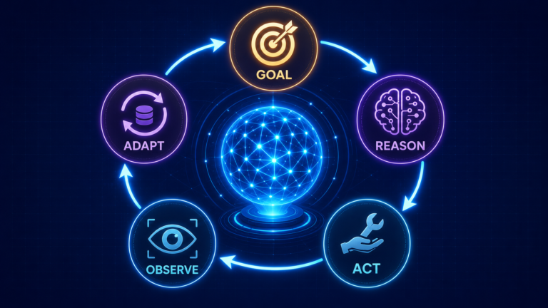
The [agent loop](/glossary/agent-loop/) is the recurring decision cycle:
Reason → Act → Observe → Update
A graph defines the larger control space in which a loop runs. One graph node may execute an entire agent loop, or each phase may be represented as a node.
The loop explains adaptive behavior. The graph explains permitted topology and routing. They are complementary.
Node vs agent
A node is an execution unit. An agent is a goal-directed system that can reason and act.
An agent can occupy one node, several nodes, or an entire subgraph. A deterministic node has no independent goal and should not be called an agent.
This distinction helps with cost and evaluation. Node-level tests can validate parsing, permissions, or state updates without invoking a model.
Node vs tool
A tool is a capability exposed for invocation. A node is a position in control flow.
A node may call a tool. An agent inside a node may select among tools. A graph edge may route to a dedicated tool-execution node.
Do not use the terms interchangeably:
- Tool contract: inputs, outputs, permission, side effect.
- Node contract: required state, state updates, transition outcomes.
Graph execution vs multi-agent system
A graph can contain one agent, many agents, or no agents. A [multi-agent system](/glossary/multi-agent-system/) contains multiple goal-directed agents that coordinate.
Examples:
- One agent plus retrieval, validation, and approval nodes: graph, not necessarily multi-agent.
- Supervisor and three specialist agents represented as nodes: graph and multi-agent.
- Deterministic data pipeline with nodes and edges: graph, not agentic.
Do not infer autonomy or collaboration from the diagram shape.
Checkpoints and persistence
A checkpoint stores a snapshot of graph state at a defined point. It supports:
- resuming after a process restart;
- waiting for a tool or human;
- retrying from a safe boundary;
- inspecting historical state;
- replaying a failed path;
- avoiding repeated expensive work.
LangGraph’s persistence documentation separates thread-scoped checkpoints from stores used for longer-term, cross-thread memory. That distinction mirrors a general architecture rule: recovery state for this run is not the same as agent memory across runs.
Checkpoint before or after side effects based on the transaction model. If a tool call succeeds but the checkpoint fails, the system must avoid duplicating the action when it resumes.
Deterministic vs model-driven transitions
Deterministic transitions provide:
- repeatability;
- auditability;
- predictable latency;
- easy unit testing;
- stronger policy enforcement.
Model-driven transitions provide:
- semantic classification;
- adaptation to ambiguous input;
- flexible strategy selection;
- handling of cases not captured by simple rules.
The strongest design often uses both:
- the model proposes one of a small set of routes;
- code validates the route and permissions;
- the graph performs the transition;
- evaluation measures routing quality.
Do not use an LLM to decide a rule already known exactly.
Practical example: support-case resolution
A support graph begins at Understand Request. A router classifies the case.
- A policy question moves to retrieval.
- An account diagnostic moves to a read-only tool.
- A high-risk request moves to human review.
All branches return to Evaluate. If evidence is sufficient and the proposed response passes policy checks, the graph finishes. If a transient tool error occurs and attempts remain, it enters RETRY and returns to the tool node. If evidence is missing, it asks the user a clarifying question and checkpoints the run.
The state machine records whether the case is working, waiting, evaluating, completed, or failed. The graph records which work can follow each outcome.
This separation makes the system resumable and prevents a model from skipping approval because it “believes” the answer is safe.
Why this architecture helps production agents
Visibility
Operators can see the current node, state, route, attempts, and pending dependency.
Recovery
The system can resume from a checkpoint instead of replaying the entire conversation.
Safety
Illegal transitions and unapproved paths can be blocked in code.
Evaluation
Teams can measure routing accuracy, node failure rates, loop counts, and terminal outcomes.
Change control
A workflow version can define exactly which graph and transition rules produced a result.
Cost control
Deterministic nodes can replace unnecessary model calls, and loops can enforce budgets.
Common architectural mistakes
Making the graph too granular
Representing every prompt and parser as a node creates visual noise and operational overhead. Choose boundaries that matter for state, recovery, routing, or ownership.
Hiding transitions inside nodes
If a node silently calls several agents and tools, the visible graph no longer explains execution. Trace nested work or use a subgraph.
Letting models invent node names
Map model output to a validated route registry.
Mixing state with transcript
Keep critical counters, approvals, and statuses in structured fields.
Retrying side effects blindly
Use idempotency keys, status checks, and safe checkpoint boundaries.
Having no terminal failure
Not every run can succeed. Model blocked, cancelled, insufficient-evidence, and policy-denied outcomes explicitly.
Assuming a graph guarantees reliability
A diagram does not provide persistence, concurrency control, authorization, or observability. The runtime implementation must do that work.
My take
Use graphs and state machines to expose the decisions that must be controlled—not to turn every agent into a maze of boxes.
If a task is linear and short, ordinary code may be clearer. When the process branches, waits, retries, or has consequential transitions, explicit nodes, state, and terminal outcomes become a production advantage.
Sources
- LangGraph Graph API Overview defines state, nodes, and edges as the core graph concepts.
- LangGraph Persistence documents checkpoints for thread-scoped state and stores for cross-thread memory.
- Statecharts: A Visual Formalism for Complex Systems introduces statecharts and links the formalism to state-machine modeling for complex software behavior.
Continue learning
Review [How AI Agents Work](/how-ai-agents-work/) for the inner loop, then use [Reflection in AI Agents](/reflection-in-ai-agents/) to understand when an evaluation node should revise or retry.